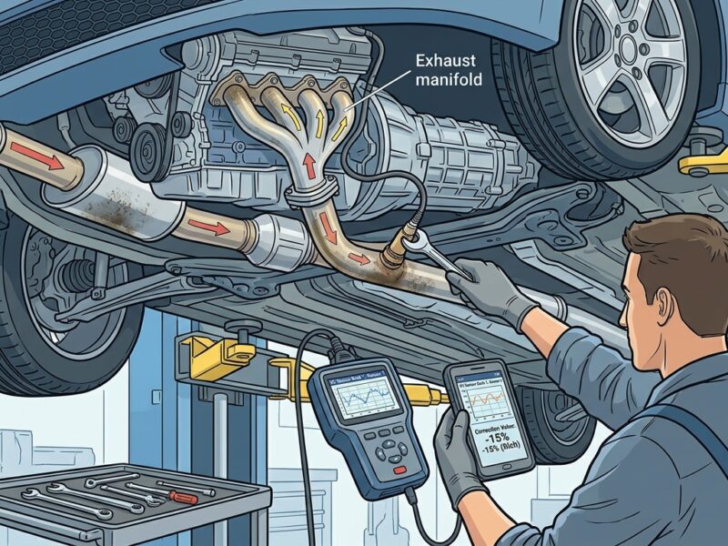
MAF Sensor
There are two uses for MAF. Both the wire and the film are heated. A hot wire measures the amount of air that enters to check the signal or voltage. The voltage of the signal is positive. Positive prob will be set by you. To check the voltage, turn on the ignition. It is between 2.5 and 3.5. Air flow is measured by hot film. MAF is located before to the throttle position.
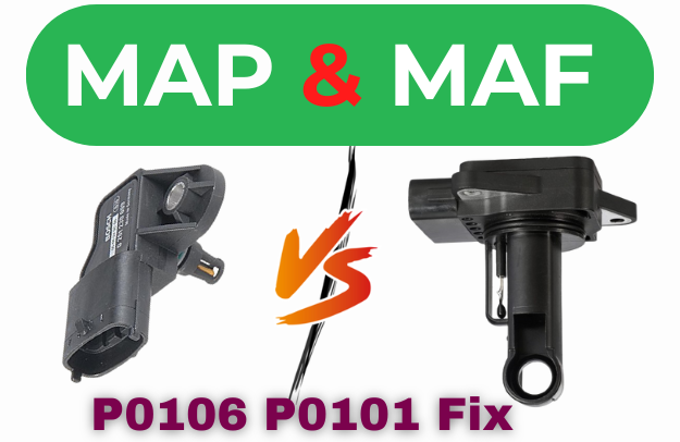
MAP sensor
For fuel injection, the ECU uses the MAP reading. It is situated on the intake manifold. After detecting vacuum pressure, it signals the ECU, which subsequently regulates fuel injection.
Wiring diagram basics of MAP and MAF Sensor
For wire design, the process is essentially the same. It has five-volt wire, ground, and map signal. It contains several colored wires. Set the multimeter to 20 volts. Verify 5 volts. To verify that the ground set multimeter is connected Put a probe on the sensor wire and another on the battery. Give the throttle and start the engine. The signal wire’s voltage should be reduced. Car speed and voltage should be directly proportional. If applying race causes voltages to drop, the MAP sensor is fixed. Using the same process, the four wire map sensors are examined. It has a signal wire for IAT. The MAP sensor has five wires that come straight from the ECU, with the exception of a 12-volt current wire, and should have a voltage between 1.25 and 1.45. Remember only the voltage, not the colors of the wire. Voltage shows the IAT and signal cable. You will get reading around 1.11 volt on MAF signal IAT hot 5V+ IAT signal 1.35V
Data trouble code related MAF and MAP
Five MAP codes If you obtain these codes, replace the sensor. MAF sensor-related codes Between P0100 and P0104 They point to a problem with the MAF sensor.